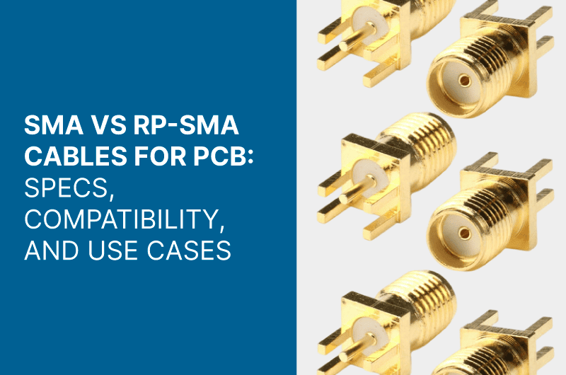
SMA vs RP-SMA cables for PCB are essential for various applications in telecommunications. Understanding their specifications and compatibility is crucial for selecting the right connector type for designs. This article explores the technical differences, use cases, and performance metrics of SMA and RP-SMA connectors. It emphasizes their importance in custom RF projects and helps guide effective integration into PCB assemblies.
Understanding SMA and RP-SMA Connectors
The SMA and RP-SMA connectors play a critical role in modern communication systems, serving distinct functions while maintaining similar physical characteristics. This section delves into their individual attributes, historical context, and common applications.
Overview of SMA Connectors
The SubMiniature A (SMA) connector is a well-established coaxial connector known for its compact design and efficiency in high-frequency applications. It has become a standard choice in various sectors, including telecommunications and electronics.
Historical Development
Introduced in the 1960s, the SMA connector was designed to handle radio frequency (RF) signals with remarkable stability. Its debut was pivotal in enhancing equipment performance in fields ranging from scientific research to military communications. Over the decades, the SMA connector has been refined and standardized to meet evolving technological demands and has solidified its status within the industry.
Typical Applications
Due to its reliable performance, the SMA connector finds extensive application across several domains:
- Telecommunications: Widely used in base stations and antennas.
- Testing Equipment: Preferred in laboratories for accurate signal measurements.
- Consumer Electronics: Found in devices that require reliable signal transmission, such as high-definition televisions.
Furthermore, the connector’s ability to operate at frequencies up to 6 GHz makes it suitable for various RF applications, ensuring robust communication and minimal signal loss.
Overview of RP-SMA Connectors
The Reverse Polarity SMA (RP-SMA) connector was developed in response to regulatory requirements that aim to mitigate interference from high-gain antennas, especially in wireless applications. This design innovation maintains the compactness of SMA connectors while ensuring compliance with specific FCC regulations.
FCC Regulations and Reverse Polarity
The introduction of RP-SMA connectors was a direct response to the FCC’s regulations aimed at preventing unauthorized interference in wireless communications. By reversing the pin configuration compared to standard SMA connectors, RP-SMA ensures that only antennas designed for these connectors can be connected, thereby preventing modifications that could lead to signal disruption. This feature is particularly important for consumer-grade wireless devices, which are often used in residential and commercial settings.
Common Use Cases
The RP-SMA connector is prevalent in scenarios where regulatory compliance and performance are paramount:
- Wireless Routers: Found in most consumer-grade Wi-Fi routers to ensure adherence to FCC standards.
- Surveillance Systems: Used in cameras that rely on wireless connectivity for transmitting data.
- Mobile Communication Devices: Equipped in smartphones and other handheld devices that require RF transmission.
This connector’s design allows for higher frequency applications that extend beyond 10 GHz, making it suitable for advanced wireless technologies, including modern Wi-Fi standards.
Technical Specifications
Understanding the technical specifications of SMA and RP-SMA connectors is essential for optimizing performance in various applications, particularly in PCB design. These specifications encompass connector construction, material types, and electrical performance metrics.
Connector Construction and Materials
The construction and materials used in SMA and RP-SMA connectors play a significant role in their durability and performance. These connectors are designed to withstand the rigorous demands of high-frequency applications.
Material Composition
Both SMA and RP-SMA connectors primarily utilize brass for their construction, often plated with nickel to enhance resistance to corrosion and wear. This combination ensures that the connectors maintain integrity under different environmental conditions. Additionally, the insulative materials employed, such as PTFE (Polytetrafluoroethylene), minimize signal loss and maintain performance consistency across a range of frequencies.
Size and Dimensions
In terms of dimensions, SMA and RP-SMA connectors generally share similar physical characteristics. Typically, these connectors feature a diameter of approximately 0.25 inches. While both types maintain this size, the internal pin configuration differs significantly, impacting their compatibility and application. The standard height for these connectors is designed to accommodate various PCB layouts without adding unnecessary bulk.
Electrical Performance Metrics
The electrical performance of SMA and RP-SMA connectors is a critical factor that affects their utility in high-frequency applications. These metrics include frequency range, signal transmission capabilities, attenuation, and overall signal loss.
Frequency Range and Signal Transmission
SMA connectors are rated for frequencies up to 6 GHz, making them suitable for various radio frequency (RF) applications, including amateur radio, television broadcasts, and some military systems. These connectors excel in environments where a reliable connection and minimal interference are paramount.
On the other hand, RP-SMA connectors can support frequencies exceeding 10 GHz. This capability is particularly beneficial in data transmission applications, especially within modern wireless networking technologies like WiFi. The ability of RP-SMA connectors to handle higher frequencies is attributed to their unique pin configuration, which accommodates enhanced signal integrity.
Attenuation and Signal Loss
Both SMA and RP-SMA connectors exhibit low attenuation characteristics, which is vital for preserving signal strength over long distances. Typically, SMA connectors have a reduced signal loss due to their robust design, allowing for effective transmission in applications where maintaining signal fidelity is critical.
RP-SMA connectors, while also exhibiting low loss, are optimized for specific applications, particularly those that require compliance with FCC regulations. Consequently, slight differences in attenuation may be observed, influenced by factors such as cable type and length when connecting to other components in a network.
Comparing SMA and RP-SMA: Key Differences
Understanding the distinctions between SMA and RP-SMA connectors is essential for making informed decisions in design and application.
Physical and Mechanical Differences
The physical and mechanical characteristics of SMA and RP-SMA connectors are one of the most significant areas of differentiation. Though they may appear similar externally, their internal configurations affect their functionality and compatibility.
Pin Configuration Variations
One of the primary differences between SMA and RP-SMA connectors lies in the pin configuration. In a standard SMA connector, the male connector features a central pin, while the female connector has a receptacle designed to accept this pin. Conversely, RP-SMA connectors have reversed this configuration. The male RP-SMA connector has a receptacle for the pin, while the female RP-SMA connector houses the pin itself.
This reversal in configuration, referred to as reverse polarity, is designed to comply with FCC regulations aimed at preventing unintentional interference from high-gain antennas in wireless communication devices. This fundamental difference leads to significant implications for compatibility since it can result in errors in connection if users do not recognize these distinct pin arrangements.
External Threads and Locking Mechanisms
Another important physical difference is found in the external threads of the connectors. SMA connectors typically come with a standard threaded coupling mechanism, which ensures a secure and reliable connection. Conversely, RP-SMA connectors also employ a threaded system but may be designed to couple differently, optimizing the connection to meet regulatory requirements.
Additionally, the locking mechanisms of these connectors may differ. SMA connectors utilize standard locking methods while RP-SMA designs are often adapted to ensure compliance with specific usage scenarios in wireless technologies. These differences highlight the necessity to use the correct type of connector based on application needs to secure a stable connection.
Interoperability and Adaptability
Interoperability is a critical consideration when working with SMA and RP-SMA connectors, particularly in complex communication systems where various components must function collaboratively. Understanding how these connectors interact is vital for designers and engineers engaged in PCB projects.
Compatibility Issues and Solutions
While SMA and RP-SMA connectors have similar mechanical designs, the differences in pin configuration create notable compatibility challenges. It is not uncommon for engineers to accidentally connect these types of connectors, only to realize that they cannot transmit signals effectively due to their incompatible designs. This scenario underscores the importance of awareness regarding the specific connector type being utilized.
To address such compatibility issues, manufacturers have designed adapters that convert SMA connectors to RP-SMA and vice versa. These adapters serve as a practical solution, enabling mixed-connector systems to function together seamlessly. However, caution should be exercised regarding the potential for signal loss and reflection that may arise when using connectors and adapters not optimized for one another.
Using Adapters Effectively
Using adapters effectively is essential for maintaining signal integrity between different connector types. When selecting an adapter to bridge SMA and RP-SMA connectors, prioritizing high-quality components that minimize signal loss is crucial. The choice of adapter should also consider the frequency and application specifications to ensure optimal performance.
In addition to selecting appropriate adapters, users should be aware of installation practices. Ensuring that connections are secure and free from physical damage can help mitigate signal degradation when using adapters. As a result, specialized installation tools and proper alignment techniques are encouraged to maintain the quality of signal transmission across connection points.
Use Cases in PCB and Custom RF Projects
The implementation of SMA and RP-SMA connectors in PCB and custom RF projects is essential for ensuring reliable signal transmission and effective communication. This section provides insight into how these connectors are utilized in various applications, the nuances of integration in PCB assemblies, and their specific roles in customized designs.
Integration in PCB Assemblies
Integrating SMA and RP-SMA connectors into PCB designs requires careful consideration to maximize performance and reliability. Professionals in the field focus on effective layout planning, ensuring that connectors’ positions facilitate optimal signal pathways while minimizing interference.
Designing for Optimal Performance
When designing a PCB that incorporates SMA or RP-SMA connectors, it is critical to consider several factors:
- Signal Pathways: The routing of traces should be designed to minimize the distance between the connector and the active circuit components. Shorter paths help in reducing signal loss and maintaining signal integrity.
- Grounding Techniques: Proper grounding is essential for reducing electromagnetic interference (EMI). Both types of connectors require a well-designed ground plane to ensure that the connectors perform optimally during operation.
- Impedance Matching: Ensuring the impedance of the PCB layout matches that of the cables used helps prevent reflections and losses. Careful attention to trace width and spacing is vital in achieving the desired impedance.
These design elements contribute significantly to the overall performance of the RF systems utilizing these connectors.
Challenges and Considerations
While integrating SMA and RP-SMA connectors into PCB assemblies, there are challenges that designers often face:
- Space Constraints: Depending on the PCB size, accommodating these connectors without compromising other components can be a challenge. This sometimes requires creative routing and placement strategies.
- Thermal Management: Connectors can introduce heat into a system. Adequate thermal management must be integrated into designs to prevent overheating, which could compromise performance and reliability.
- Connector Variability: The market has various manufacturers and types of SMA and RP-SMA connectors, each with different specifications. Ensuring consistency in choice is vital to avoid compatibility issues during assembly.
Custom RF Projects and Designs
In the arena of custom RF projects, the choice of connectors has a direct impact on the functionality and success of the designed system. These projects often require specific characteristics that SMA and RP-SMA connectors can offer.
Selecting the Right Connector Type
Choosing between SMA and RP-SMA connectors often hinges on the intended application and regulatory compliance:
- Frequency Requirements: Projects requiring higher frequency operations typically favor RP-SMA connectors due to their capability to handle frequencies up to 10 GHz, whereas SMA connectors are usually suited for lower frequency applications.
- Regulatory Compliance: If a custom RF project needs to meet specific FCC regulations, opting for RP-SMA connectors is often preferred. This is particularly relevant for wireless applications where interference with other signals must be minimized.
- Connector Availability: Depending on market acceptance and availability, selecting one connector type over the other might influence the ease of sourcing components for ongoing projects.
Enhancing Signal Integrity
Maintaining signal integrity in custom RF designs is paramount. Several best practices are recommended to enhance performance:
- Cable Quality: Utilizing high-quality cable assemblies that match the chosen connector type can significantly enhance signal integrity. Poor cable quality can lead to increased attenuation and degradation.
- Minimizing Flex and Stress: Ensuring that cables and connectors experience minimal bending and physical stress during installation helps maintain performance over time. Reinforced connectors can also alleviate stress-related issues.
- Testing and Validation: Rigorous testing to validate performance under expected operational conditions is crucial. This assurance helps prevent failures in actual use, thereby solidifying project reliability.
These strategies play a vital role in ensuring that custom RF projects operate efficiently and effectively, capitalizing on the strengths of SMA and RP-SMA connectors.
FAQs: Addressing Common Questions
This section addresses frequently asked questions to clarify the differences and considerations when choosing between SMA and RP-SMA connectors. Understanding these common inquiries can enhance the decision-making process for both new users and seasoned professionals.
Choosing Between SMA and RP-SMA
Selecting the right connector is essential for ensuring optimal performance in various applications. Here are key considerations that can help guide the choice between SMA and RP-SMA connectors:
- Application Requirements
The application’s specific needs should dictate the choice of connector. For instance, SMA connectors, with a frequency range up to 6 GHz, excel in applications requiring lower-frequency transmissions, while RP-SMA connectors can handle higher frequencies exceeding 10 GHz, making them ideal for modern WiFi and RF communications. - Compatibility with Existing Equipment
It is crucial to ensure that the connector type aligns with the existing devices or systems. SMA and RP-SMA connectors are physically compatible but not interchangeable due to their differing pin configurations. Any misalignment can result in poor performance or no signal transmission. - Regulatory Compliance
For devices that need to comply with FCC regulations, particularly in wireless communications, RP-SMA connectors are necessary. They prevent unauthorized access to sensitive frequencies and ensure compliance with communication standards. - Future-Proofing
Consider upcoming technological advancements when selecting connectors. If the project involves future wireless upgrades, opting for RP-SMA connectors may be more beneficial due to their higher frequency capabilities.
Best Practices for Installation and Maintenance
Proper installation and maintenance are essential to ensure performance and longevity for both SMA and RP-SMA connectors. Below are recommendations to follow during these processes:
- Proper Tool Use
Using the right tools for installation is critical. Employ crimping tools designed for RF cables and connectors to achieve secure connections. This reduces the risk of connection failures caused by improper clamping or loose connections. - Avoiding Excessive Force
During installation, avoid applying excessive force. Over-tightening can lead to damage to the connector or PCB. Ensure that connections are snug but not overtightened to maintain signal integrity. - Regular Inspections
Perform regular inspections on the connectors to check for wear and tear. Look for signs of physical damage, corrosion, or discoloration, which can indicate compromised performance. - Clean Connections
Keep the connections clean and free of dust or contamination. Use appropriate cleaning solutions and lint-free cloths to maintain the integrity of the connectors. Dirt and grime can lead to signal loss and degraded performance. - Documentation
Maintain a detailed record of all installation and maintenance activities. This documentation can prove invaluable for troubleshooting and ensuring that the correct procedures are followed over time.
If you would like to receive a quote for any of custom cables or connectors, please do not hesitate to contact us by sending an email to sales@readytogocables.com or calling in the USA this phone number (682-325-1944).